This circuit has a lot going for it. For one thing, it only consists of two
transistors, two capacitors and four resistors. That also means it
consumes very little power. You can control the flash rate by changing
the size of the 100k resistors (100k makes for a pretty slow rate).
You can also control the duty cycle by using resistors of different
values on the two sides. The 470 ohm resistors control the current
through the LEDs. Normally you want to limit this to 20mA, but to
conserve battery power, you may need to limit it even further. You
can also connect several LEDs in series, instead of using only one
for each side. With red LEDs (1 per side) and the values shown,
the circuit draws about 11mA.
 more
moreBasic LED flasher circuit using NE555 timer IC
This circuit consumes more power, but it's advantage is when
you need a variable flash rate, like for strobe circuits. You can
actually use this circuit as a remote control for strobes that have
a remote input. Of course, it has many other applications
besides strobes.
 more
more4 Parallel LEDs flashing circuit
Nominal flash rate: 1.3 Hz. Average IDRAIN e 2 mA
LM3909 LED Flasher/Oscillator
General Description
The LM3909 is a monolithic oscillator specifically designed
to flash Light Emitting Diodes. By using the timing capacitor
for voltage boost, it delivers pulses of 2 or more volts to the
LED while operating on a supply of 1.5V or less. The circuit
is inherently self-starting, and requires addition of only a battery
and capacitor to function as an LED flasher.
Packaged in an 8-lead plastic mini-DIP, the LM3909 will operate
over the extended consumer temperature range of
b25§C to a70§C. It has been optimized for low power drain
and operation from weak batteries so that continuous operation
life exceeds that expected from battery rating.
Application is made simple by inclusion of internal timing
resistors and an internal LED current limit resistor. As
shown in the first two application circuits, the timing resistors
supplied are optimized for nominal flashing rates and
minimum power drain at 1.5V and 3V.
more pdf
12 LED Flasher
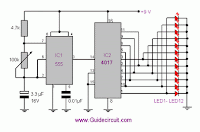
LED flasher in this circuit use 12 LED it can show 2 style .
12 LED Flasher
LED flasher in this circuit use 12 LED it can show 2 style .
The circuit consist 2 section

more
1.5 volt dual LED flasher Circuit
This 1.5 volt led fasher runs more than a year on a single 'd" cell
and alternately flashes 2 LEDs at about a 1 second rate. The
circuit employs a 74HC14 CMOS hex inverter that will operate
at very low voltages (less than 1 volt). One section is used as a
squarewave oscillator (pins 1 and 2), while the others are wired
to produce a short 10mS pulse on alternate edges of the square
wave so the LEDs will alternate back and forth.


